The connector’s signal contact had a spring structure, and in many cases it became too complex a structure to obtain sufficient memory and force. Although it was able to cope with the USB 2.0 specification that was widely used at that time, it had a problem handling signals faster than 5Gb/s for USB 3.0 devices. The first version of the Mag-Fit concept sufficiently protected the connector and was user-friendly, but there was a limit to high-speed signal transmission.

Disconnection can be achieved with a relatively small rotational force or a slight twisting action. Through the use of a magnet, it is possible to guide the connector to the proper position with the magnetic force alone. The opposite/receptacle connector has a mating contact and a structure that is pressed against the pad by a spring. This is a very simple configuration that maintains a small size and can be produced at a low cost. In this type, the plug side has only a contact pad. This concept, called the Mag-Fit, is classified as a surface type connection, rather than an insertion type, and was adopted in an industry standard connector. To combine user-friendliness and miniaturization, the concept of a connector with a shutter that could protect the contacts was developed.
#POGO PIN TYPES PORTABLE#
However, this large connector wasn’t suitable for portable equipment and, in a miniaturized version, its contacts were too weak. The solution required a design that would prevent breakage yet deliver performance in a small, thin, and elegant end product.ĭesigners examined various concepts, including a structure in which the cradle side connector rotated and followed up when unmating, as well as an option with a shutter, but the most user-friendly connector seemed to be a so-called brand-mate-type connector with a magnetic port. Another effective countermeasure could have been to design a guide that was slightly larger than the connector, but that is contrary to the small, thin connector size demanded by end devices like smartphones and tablets.

A wrapping structure would have restricted the direction and prevented damage problems but would have also limited the versatility of the design to a single, specific device. The first step in the redesign process identified that the angle of insertion and extraction had to be controlled to protect the connector from damage. The failure occurred when removing the devices from the cradle. Although the standard micro USB and micro HDMI connectors were widely used in the device market, the cradle device was designed for use across multiple smartphone and tablet product lines, so its structure could not be designed to a specific body.


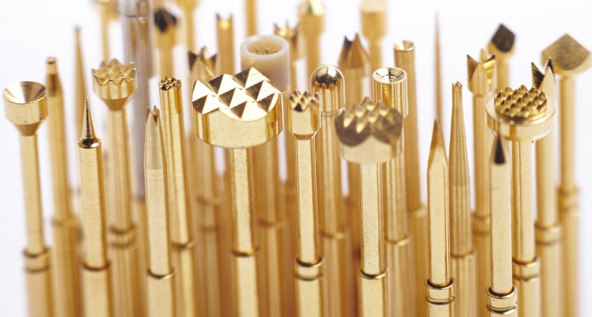
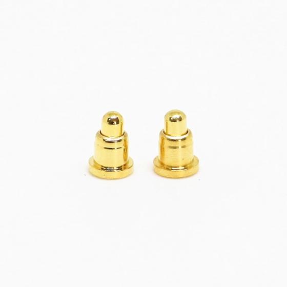
When a major OEM brand of mobile phones exhibited a cradle device for their smartphone and tablet at the Consumer Electronics Show a few years ago, the interconnect failed on the first day of the show. Here’s how they did it.īy Nobukazu Kato, ACES Electronics, and Sam Martin, ACES North America A very public failure of a proven connector spurred a team of designers to engineer a flexible and dependable new solution using pogo pins. Industry-standard connectors don’t always get the job done.


 0 kommentar(er)
